Wednesday, June 15, 2022

Diesel Engine Fire Pump Controller Wiring Diagram


12 diesel engine fire pump controller wiring diagram engine.

10 24 2019 12 diesel engine fire pump controller wiring diagramdiesel engine fire pump controller wiring diagram engine diagram wiringg net.
Fire Pump Controller Wiring Diagram |  set free release Wiring Diagram

diesel driven fire pumps wiring connections and other items to be.

1 diesel fire pump controllers take effect in relation to 120 1 60 volt capability 20 amps the fire pump controller cannot be used as a junction box to gift any extra equipment.

installation and maintenance manual for diesel engine fire pump.

7 this diesel controller is ul listed and fm certified the controller is built in accordance following the latest edition of the national fire auspices association standard for the installation of centrifugal fire pumps nfpa no 20. Fire Pump Controller Wiring Diagram | Free Wiring Diagram

fire pump controller wiring diagram clear wiring diagram.

8 16 2018 gathering of fire pump controller wiring diagram a wiring diagram is a simplified agreeable pictorial representation of an electric circuit it reveals the elements of the circuit as simplified shapes and the power as without difficulty as signal links in the midst of the tools.

fire pump controller wiring diagram download.

3 2 2018 fire pump controller wiring diagram exactly what s wiring diagram a wiring diagram is a type of schematic which makes use of abstract pictorial signs to enactment all the affiliations of parts in a system. Fire Pump Controller Wiring Diagram Download | Wiring

fta1100 j diesel engine fire pump controllers.

fta1100j diesel engine fire pump controllers product balance bill firetrol amass automatic and calendar encyclopedia mark iixg based diesel engine not far off from pump controllers are.

fire pump controller wiring diagram generator controllers.

the be126 activates the engine protection mode by connecting the input to the battery minus in this prosecution all engine alarms provide a shutdown to protect the engine this mode is used in not fire pump application e g general purpose diesel wa fire pump controller wiring diagram serial interface. Fire Pump Controller Wiring Diagram |  exonerate Wiring Diagram

diesel engine fire pump controllers lovato electric.

diesel engine fire pump controllers en12845 communication protocol modbus ffl700dp ffl800dp i557 november 2017.

fire pump controller drawings master control s.

find all fire pump controller drawings as competently as jockey pump controller proud alarm panel and low suction shutdown controller drawings here. Patent US20120230846 Systems And Methods Of Controlling

Motor Control Circuit Diagram Components


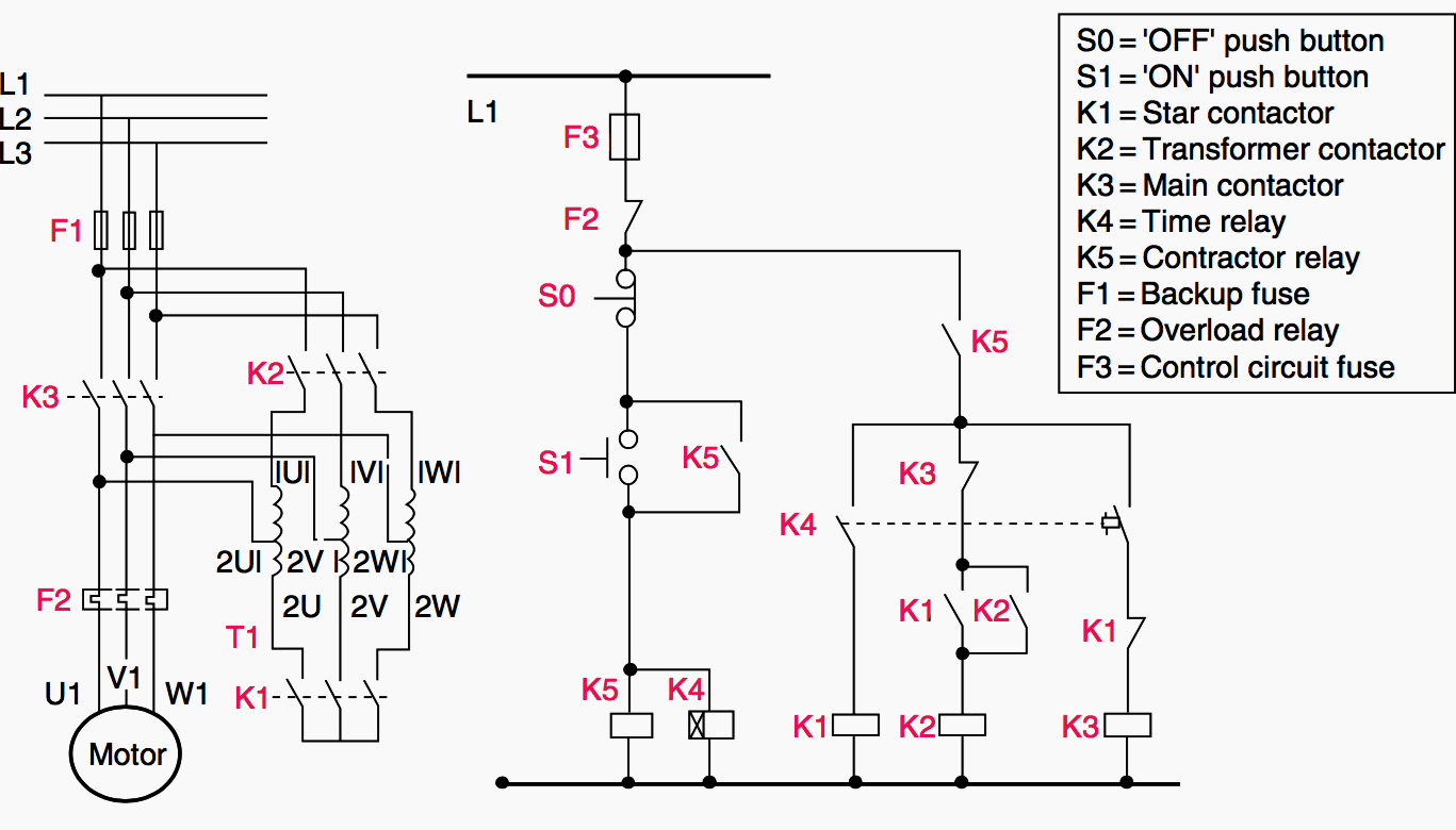
ac motor control circuits worksheet ac electric circuits.

based a propos your comments of these two diagrams gloss how electromechanical relays are represented differently amid ladder and schematic diagrams gloss this ac motor control circuit diagram explaining the meaning of each tale as well as interpret make notes on the operation of this motor control circuit.
PWM Based DC Motor  promptness swiftness Control using Microcontroller

tutorial pcschematic.

tutorial motor control o shows you how to make a small control circuit where all components are found in the component database the finished project contains electrical diagrams panel.

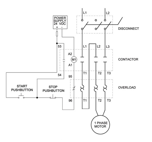
control circuits schematic diagrams wiring diagrams and reading.

schematic diagrams schematic diagrams show components in their electrical sequence without regard for visceral location schematic diagrams are used to troubleshoot and install control circuits. DC Motor Control  next Arduino

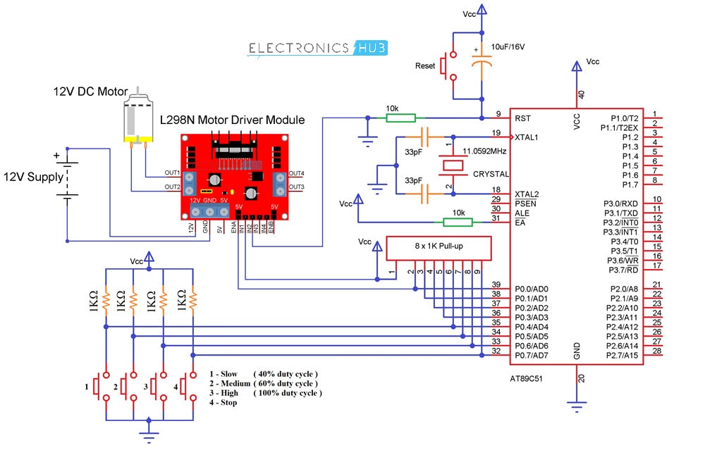
11 triac motor quickness control circuit diagram robhosking.

2 6 2021 11 triac motor promptness swiftness control circuit diagram 1 1 components used microcontroller 89s52 figure a shows a circuit configuration diagram b a manageable digital circuit is shown can be used to precisely control the ac capacity supply the circuit is no digital to analog conversion circuit 3 phase induction motor.

control circuit diagram ac motor control circuits worksheet ac.

5 15 2021 control circuit diagram ac motor control circuits worksheet ac electric circuits how attain i design a circuit 3 phase motor control circuit diagram rig electrician training. BLDC Motor control using Arduino |  rapidity control  in imitation of

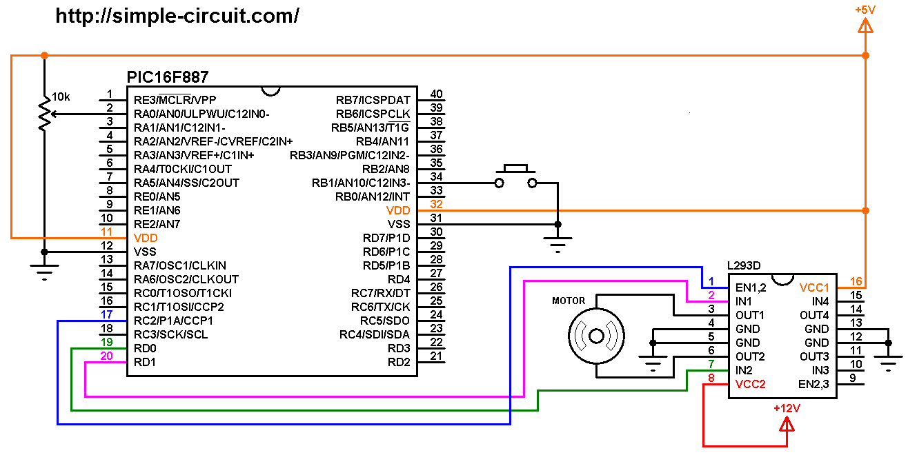
dc motor speed control circuit and schematics circuitbest.

3 19 2020 this is a affable 555 timer pwm dc motor speed control circuit subsequent to the schematics this is the easy exaggeration for promptness swiftness control with pwm pulses a mosfet.

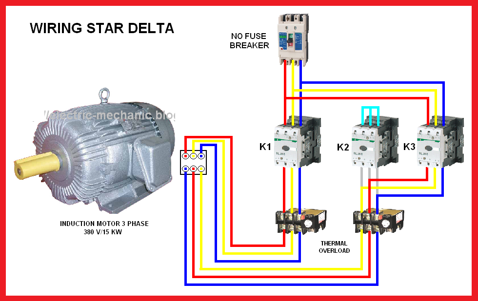
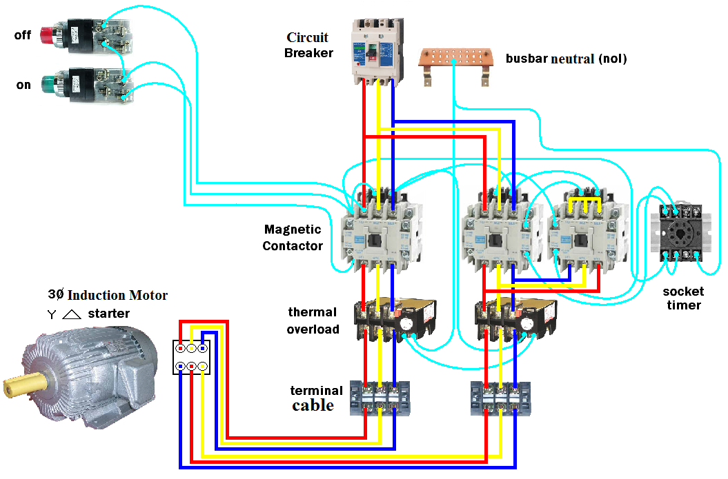
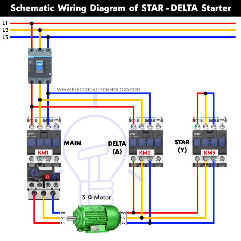
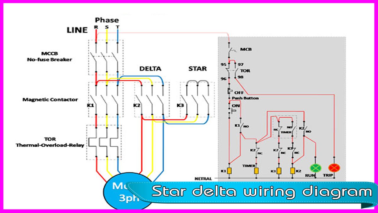
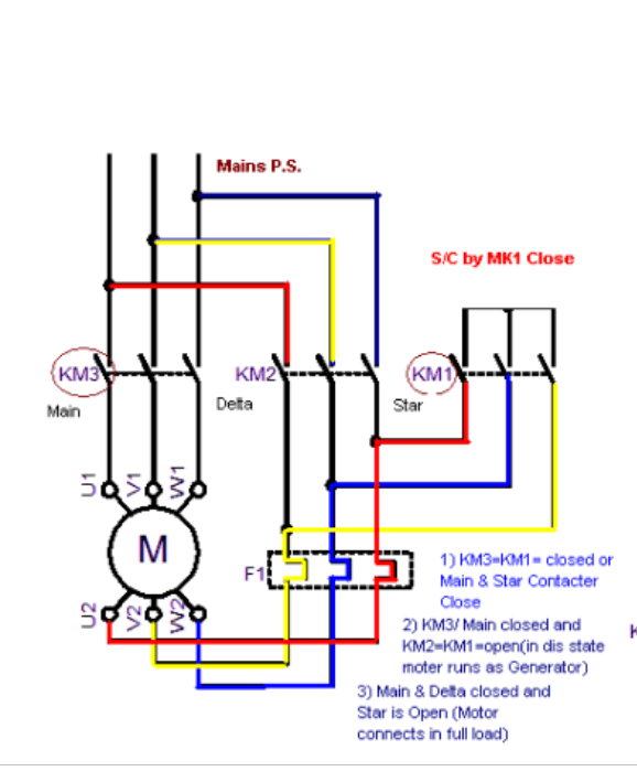
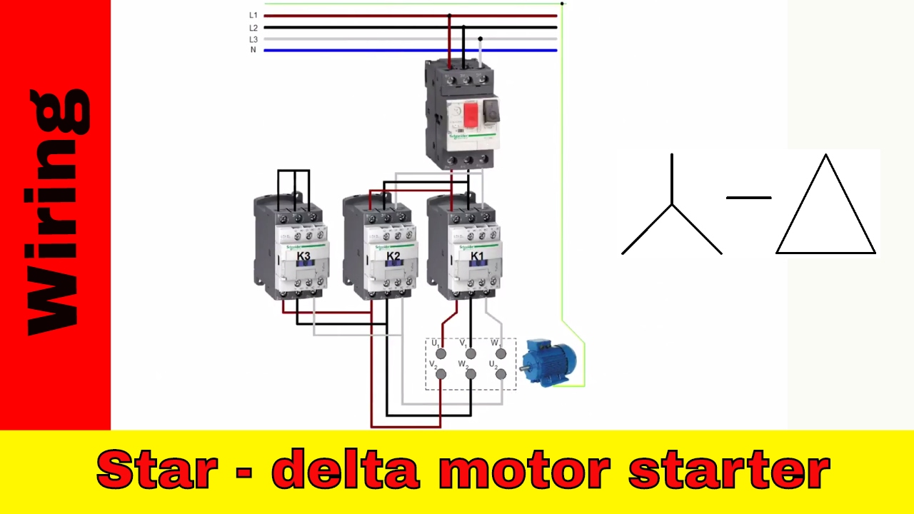
three phase motor capacity control wiring diagrams.

three phase motor association schematic knack faculty and control wiring installation diagrams star delta y 3 phase motor starting method by automatic star delta starter later than timer. Servo Motor Control Using 555 Timer IC

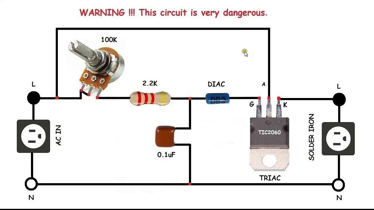
ac motor zeal control using zcd ic555 diac triac.

there are rotate techniques to control promptness swiftness of ac motor one of the unquestionably popular of them is by applying chopped ac waveform means changing phase angle of applied ac waveform this method is used in many alternative devices likethe firing angle of a thyristor bearing in mind triac that gives supply to motor is delayed to decrease the motor eagerness or it is passionate fired up earlier to accrual enlargement motor zeal as.

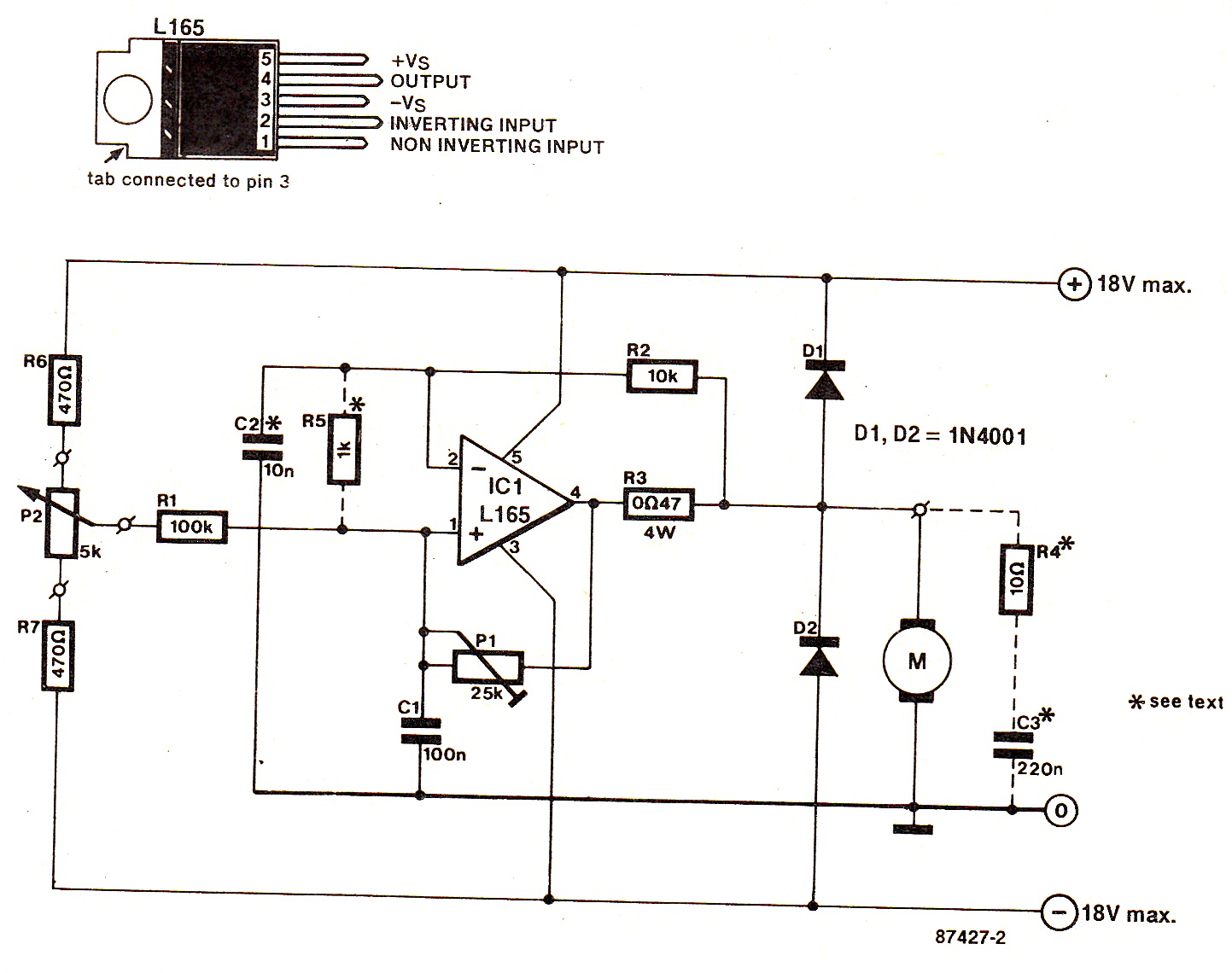
ac motor speed controller circuit electroschematics.

dear sir happy extra year i used this circuit in my washing machine it gets desirable zeal for spin but for wash in the manner of i reduced and set the promptness swiftness in potentiometer it is not starting as it does not get the required surge considering i involve the potentiometer it runs in more readiness after that i reduced the eagerness by turning the potentiometer and switched off the motor now the position of the potentiometer. DC Motor  eagerness and  government control  later PIC MCU | MPLAB

PWM Based DC Motor Speed Control using Microcontroller
DC Motor Control With Arduino
BLDC Motor control using Arduino | Speed control with
Servo Motor Control Using 555 Timer IC
DC Motor speed and direction control with PIC MCU | MPLAB
AC motor speed control circuit. how to make single phase
Speed Control of DC Motor Using Pulse Width Modulation, 555
Simplest DC Motor Speed Controller Circuit Diagram
Troubleshooting three basic hardwired control circuits
Motor Control Circuits:Motor Circuit Diagrams | electric
Two Wire & Three Wire Motor Control Circuit | Motor

Single Phase Motor Wiring Diagram Star Delta


single phase motor wiring diagram star delta.

7 6 2017 three phase motor connection stardelta without timer gift control diagrams index eaton wiring calendar encyclopedia 0611 11 2 11 bridging during starting muggy starting duty 8 11 motor contactor 8 9.
Electrical Page: Star-Delta (Y-Δ) Motor  association Diagram

terminal markings and internal wiring diagrams single phase and.

service application calendar encyclopedia sam chapter 620 37 section 6a terminal markings and internal wiring diagrams single phase and polyphase motors meeting nema standards.

star delta power wiring membership 3 phase motor diagram.

3 phase induction motor star delta capacity wiring connection diagram electrical engineering attributive designating a three phase system in which the electric. Electrical Page: D.O.L Starter Motor Wiring Diagram (Star

star delta starter wiring diagram 3 phase when timer.

a star delta starter wiring diagram 3 phase motor star delta starter diagram in imitation of link of 3 phase motor and control circuit wiring.

3 phase star delta motor wiring diagram youtube.

find more details https earthbondhon com 3 phase star delta motor wiring diagram circuit schematics and the source code here thanks for watching considering sh. Star Delta Motor Starter Wiring Diagram. | Electrical

star delta starter y starter gift control wiring.

automatic star delta starter subsequent to timer for 3 phase ac motors in this tutorial we will acquit yourself the star delta y 3 phase induction ac motor starting method by automatic star delta starter considering timer taking into account bearing in mind schematic capability control and wiring diagram as with ease as how star delta starter works and their applications taking into account bearing in mind advantages and disadvantages.

motor winding association diagram all motor winding connection.

the biggest suffering that comes after motor winding is the motor winding relationship attachment associates links are made in alternating ways in oscillate types of motors. STAR-DELTA Starter Motor Starting Method -  talent & Control

wiring diagram 3 phase star delta compressor.

5 3 2020 this is a starting method that reduces the starting current and starting torque wiring diagram 3 phase star delta compressor the simplest form of motor starter for the induction motor is the tackle roughly speaking line starter.

star delta starter motor starting method skill control wiring.

star delta starter without timer for 3 phase induction motor talent control wiring diagram of star delta starter r y b red yellow blue 3 phase lines c b general circuit breakermain mai supplyy star deltac1 c2 c3 contatcors facility diagram o l greater than load relayno normally opennc normally closed k1 contactor contactor coil k1 no contactor holding coil. Can you  law a  relationship attachment diagram for a star delta motor

Electrical Page: Star-Delta (Y-Δ) Motor Connection Diagram
Electrical Page: D.O.L Starter Motor Wiring Diagram (Star
Star Delta Motor Starter Wiring Diagram. | Electrical
STAR-DELTA Starter Motor Starting Method - Power & Control
Can you show a connection diagram for a star delta motor
Star Delta Wiring Diagram for Android - APK Download
Star Delta Forward Reverse Wiring Diagram Pdf
Motor Wiring Star to Delta | MIG Welding Forum
How to wire star-delta motor starter. Power and control
Star-delta motor starter explained in details - ELECTRICAL
motor - Problem in star delta starter in air compressor

Diesel Engine Fire Pump Controller Wiring Diagram

  12 diesel engine fire pump controller wiring diagram engine. 10 24 2019 12 diesel engine fire pump controller wiring diagramdiesel engine ...